4.1.2. TI TMS570-based BMS-Master v1.1.1
Note
The changelog for this release is found at Section 4.1.1.9.
Important
BMS-Master release TI TMS570-based BMS-Master v1.2.2 is designed and prepared for a CAN based bootloader for remote firmware update. Follow the instructions to establish bootload compatibility on older hardware.
The following specifications must be met to ensure a safe and optimal work with the BMS-Master hardware.
4.1.2.4. Bootloader Compatibility on BMS-Master prior to v1.2.2
In BMS-Master release TI TMS570-based BMS-Master v1.2.2, the CAN1 Enable and Standby signals have been wired directly to the MCU, instead of using I2C based port expander. Therefore, on BMS-Master prior to v1.2.2 the CAN1 transceiver would not be enabled during bootloader operation, lacking the feature of firmware update capability.
By desoldering populated 10kOhm pull-down resistors R6320_2 and R6321_2, the CAN1 transceiver will be enabled by default and is available during bootloader operation.
Details are shown in Fig. 4.22.
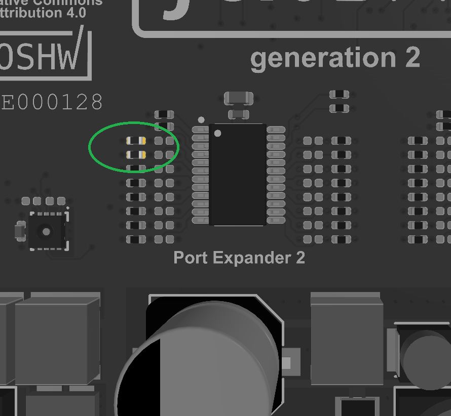
Fig. 4.22 Resistors R6320_2 and R6321_2 to be removed for compatibility with bootloader
4.1.2.5. Electrical Ratings
Description |
Minimum |
Typical |
Maximum |
Unit |
|---|---|---|---|---|
Supply Voltage Clamp 30 (VSUP_30) |
9 |
12 |
55 |
V DC |
Supply Voltage Clamp 30C (VSUP_30C) |
9 |
12 |
55 |
V DC |
Contactor Continuous Current |
– |
– |
1.8 |
A |
Contactor Feedback Supply Voltage |
– |
VSUP_30 |
– |
V |
Interlock Circuit Sink Current |
– |
10 |
– |
mA |
Idle Supply Current at 12V DC for VSUP_30 |
– |
215 |
– |
mA |
Idle Supply Current at 24V DC for VSUP_30 |
– |
160 |
– |
mA |
4.1.2.6. Mechanical Dimensions (BMS-Master PCB only)
Description |
Value |
Unit |
|---|---|---|
Width |
120 |
mm |
Length |
200 |
mm |
Height |
13 |
mm |
Weight |
129 |
g |