6.1.1. Interface LTC-6820 V1.0.3
6.1.1.1. Overview
Important
The following description only applies for the LTC6820-based
BMS-Interface Board hardware version 1.0.3.
Hint
All connector pinouts described below follow the Convention for Connector Pin Numbering.
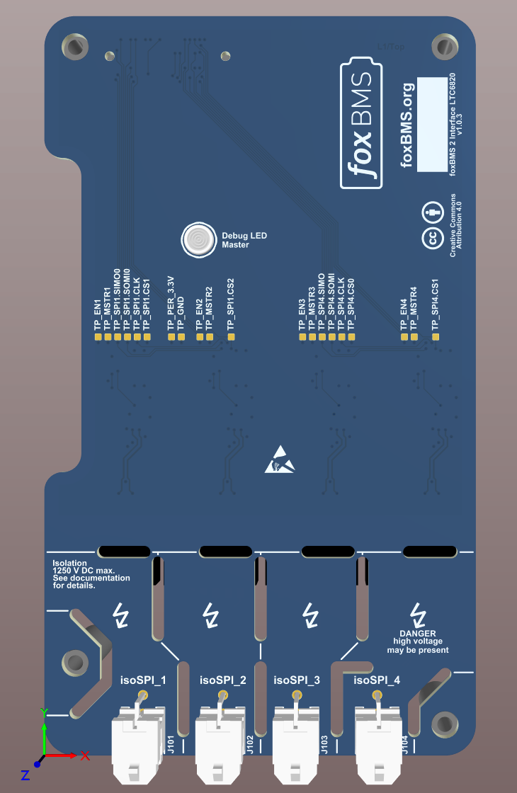
The BMS-Interface Board is used to enable communication between the BMS-Master Board and the BMS-Slave Boards. A 3D rendering of the BMS-Interface Board is shown in Fig. 6.1. The BMS-Interface Board is intended to be used together with a BMS-Master Board.

Fig. 6.1 3D rendering of the BMS-Interface Board
6.1.1.1.1. Block Diagram
This section of the documentation is not yet complete.
6.1.1.1.2. Schematic and Board Layout
More information about the board schematic and layout files can be found in section Design Resources.
6.1.1.2. Functions
6.1.1.2.1. isoSPI communication
The BMS-Interface Board offers up to four isolated isoSPI communication channels using the LTC6820 transceiver chip from Analog Devices. The LTC6820 transceivers are controlled by the SPI signals from the BMS-Master Board. The isoSPI signals are available on the connectors J101, J102, J103 and J104. The pinout is described in Table 6.1.
Pin |
Signal |
Description |
|---|---|---|
1 |
|
isoSPI positive |
2 |
|
isoSPI negative |
