5.1.1. LTC6804-1-based 12-Cell Slave v1.x.x
5.1.1.1. Overview
Important
The following description only applies for the LTC6804-1-based 12 cell
BMS-Slave Board hardware versions 1.x.x.
Hint
All connector pinouts described below follow the Convention for Molex Micro-Fit 3.0 Connector Pin Numbering.
5.1.1.1.1. Block Diagram
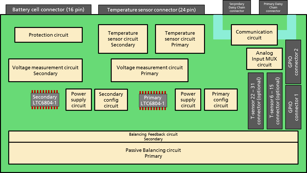
The block diagram of the BMS-Slave Board is shown in Fig. 5.1

Fig. 5.1 BMS-Slave Board 12-Cell Block Diagram
5.1.1.1.2. Schematic and Board Layout
More information about the board schematic and layout files can be found in section Design Resources.
5.1.1.1.3. Mechanical Dimensions
The size of the PCB is 160x100mm.
Pin |
Signal |
|---|---|
1 |
not connected |
2 |
|
3 |
|
4 |
not connected |
5 |
not connected |
6 |
|
7 |
|
8 |
not connected |
9 |
not connected |
10 |
not connected |
11 |
not connected |
12 |
not connected |
13 |
not connected |
14 |
not connected |
15 |
not connected |
16 |
not connected |
Note
This connector pin out is only valid for use of a foxBMS Master Interface board for the LTC6804-1 monitoring IC.
On the BMS-Slave Board, the connectors indicated as
Primary Daisy Chain connector and Secondary Daisy Chain connector in
Fig. 5.1 must be used.
Their layout is described in Table 5.5.
Pin |
Daisy Chain |
|---|---|
1 |
|
2 |
|
3 |
|
4 |
|
The OUT+ and OUT- pins of the BMS-Master Board go to the IN+ and IN- pins
of the BMS-Slave Board.
A cable with a receptable on both ends must be crimped correctly to make the
connection.
In case a second BMS-Slave Board must be connected to the daisy chain, the OUT+
and OUT- pins of the first BMS-Slave Board must be connected to the IN+ and
IN- pins of the second BMS-Slave Board.
5.1.1.2. Cell Voltage Connector on the foxBMS Slave Units
The connector indicated as Battery cell connector (16 pin) in
Fig. 5.1 has two purposes:
Supply of the BMS-Slave Board
Input of the cell voltages to the LTC6804-1 monitoring chip
The layout of the connector is described in
Table 5.6.
Up to 12 battery cells can be connected in series, between VBAT+ and VBAT-.
The BMS-Slave Board is supplied by VBAT+ and VBAT-.
The total voltage of all cells in series must be between 11V and 55V
(see [ltc_data_sheet_6804] and [ltc_data_sheet_6811]).
0- correspond to the negative pole of cell 0, 0+ to the positive pole of cell 0, 1- correspond to the negative pole of cell 1, 1+ to the positive pole of cell 1 and so one till 11+, the positive pole of cell 11. As the cells are connected in series, the positive pole of one cell is connected to the negative pole of the next cell: 0+ to 1-, 1+ to 2+ and so on.
The poles should be connected to the cell voltage connector as shown in
Table 5.6.
If less than 12 battery cells are used, information on how to connect them can be found LTC6804-1 data sheets ([ltc_data_sheet_6804] and [ltc_data_sheet_6811]).
Pin |
Battery Cell |
|---|---|
1 |
|
2 |
0+ (1-) |
3 |
2+ (3-) |
4 |
4+ (5-) |
5 |
6+ (7-) |
6 |
8+ (9-) |
7 |
10+ (11-) |
8 |
not connected |
9 |
0- |
10 |
1+ (2-) |
11 |
3+ (4-) |
12 |
5+ (6-) |
13 |
7+ (8-) |
14 |
9+ (10-) |
15 |
11+ |
16 |
|
In case no cells are available, they can be simulated with a series of voltage
divider.
A voltage supplied of 30V should be used and 12 resistors with the same value
connected in series between the positive and negative connectors of the voltage
supply.
The positive connector is linked to VBAT+, the negative connector to VBAT-
and each pole of a resistor correspond to a pole of a battery cell.
The voltage of 30V is chosen so that every simulated cell voltage lies around
2.5V, which lies in the center of the safe operating area defined by default in
the foxBMS 2 software.
5.1.1.3. Cell Temperature Connector on the foxBMS Slave Units
The connector indicated as Temperature sensor connector (24 pin) in
Fig. 5.1 is used to connect
temperature sensors to the BMS-Slave Board.
Table 5.7 describes the temperature connector.
Pin |
Temperature Sensor |
|---|---|
1, 24 |
T-Sensor 0 |
2, 23 |
T-Sensor 1 |
3, 22 |
T-Sensor 2 |
4, 21 |
T-Sensor 3 |
5, 20 |
T-Sensor 4 |
6, 19 |
T-Sensor 5 |
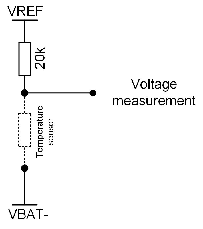
Fig. 5.2 shows the functioning of a temperature sensor.

Fig. 5.2 Temperature sensor circuit.
The voltage VREF (3V) is generated by the LTC6804-1 chip. A temperature-dependent resistor must be added to build a voltage divider (drawn as a dashed line in Fig. 5.2, not delivered with the BMS-Slave Boards). The resulting voltage is measured by the LTC6804-1 chip. Knowing the temperature dependence of the resistor, the relation between measured voltage and temperature can be determined.
A function is present in the code to make the conversion between measured voltage and temperature. It must be adapted to the temperature sensor used. In case temperatures are read incorrectly, this function is the first step to verify.
It must be noted that if no sensor is connected, 3V are measured.
If sensors are added, they must be connected between the connector pins corresponding to the sensors 0 to 5, as shown in Table 5.7.
- ltc_data_sheet_6804(1,2)
LTC6804 data sheet http://cds.linear.com/docs/en/datasheet/680412fb.pdf
- ltc_data_sheet_6811(1,2)
LTC6811 data sheet http://cds.linear.com/docs/en/datasheet/68111f.pdf


