3. The foxBMS 2 Platform
The foxBMS 2 platform consists of two main elements:
the foxBMS Master Unit and
the foxBMS Slave Unit.
The foxBMS Master Unit consists of 3 boards:
the BMS-Master Board,
the BMS-Interface Board and
the BMS-Extension Board.
An ARM-based microcontroller (Cortex-R5) is used on the BMS-Master Board.
The BMS-Master Board communicates with the outside world via a CAN bus. The current flowing through the battery system is measured via a current sensor connected to a CAN bus. The current sensor is controlled via CAN by the BMS-Master Board and sends the resulting measurement via CAN.
The foxBMS Slave Units (based on BMS-Slave Boards) are used to measure cell voltages and cell temperatures in the battery modules. The foxBMS Slave Units can be linked in series.
In order for the foxBMS Master Unit to communicate with the foxBMS Slave Units, an interface board (BMS-Interface Board) is needed. It implements the physical layer of the communication between the BMS-Master Board and the foxBMS Slave Units.
Control requests to the foxBMS Master Unit are made via CAN messages. They control the externally facing behavior of the system such as opening and closing the contactors based on the internal implementation. The foxBMS Master Unit measures the state of the battery system and decides based on the implemented algorithms the state of the contactors. The measured system state is additionally communicated through CAN messages to a superior control unit.
The BMS-Master Board also implements an interlock line. This is a fast acting interface that has to be connected through crucial system components such as the foxBMS Master Unit, emergency stop switch, master service disconnect switches and similar devices. The interlock line can be opened by any connected device. It is possible to define a system behavior in the case that the interlock line has been opened such as the transition to an application-specific safe-state, which could be the opening of all contactors.
See Fig. 3.1.
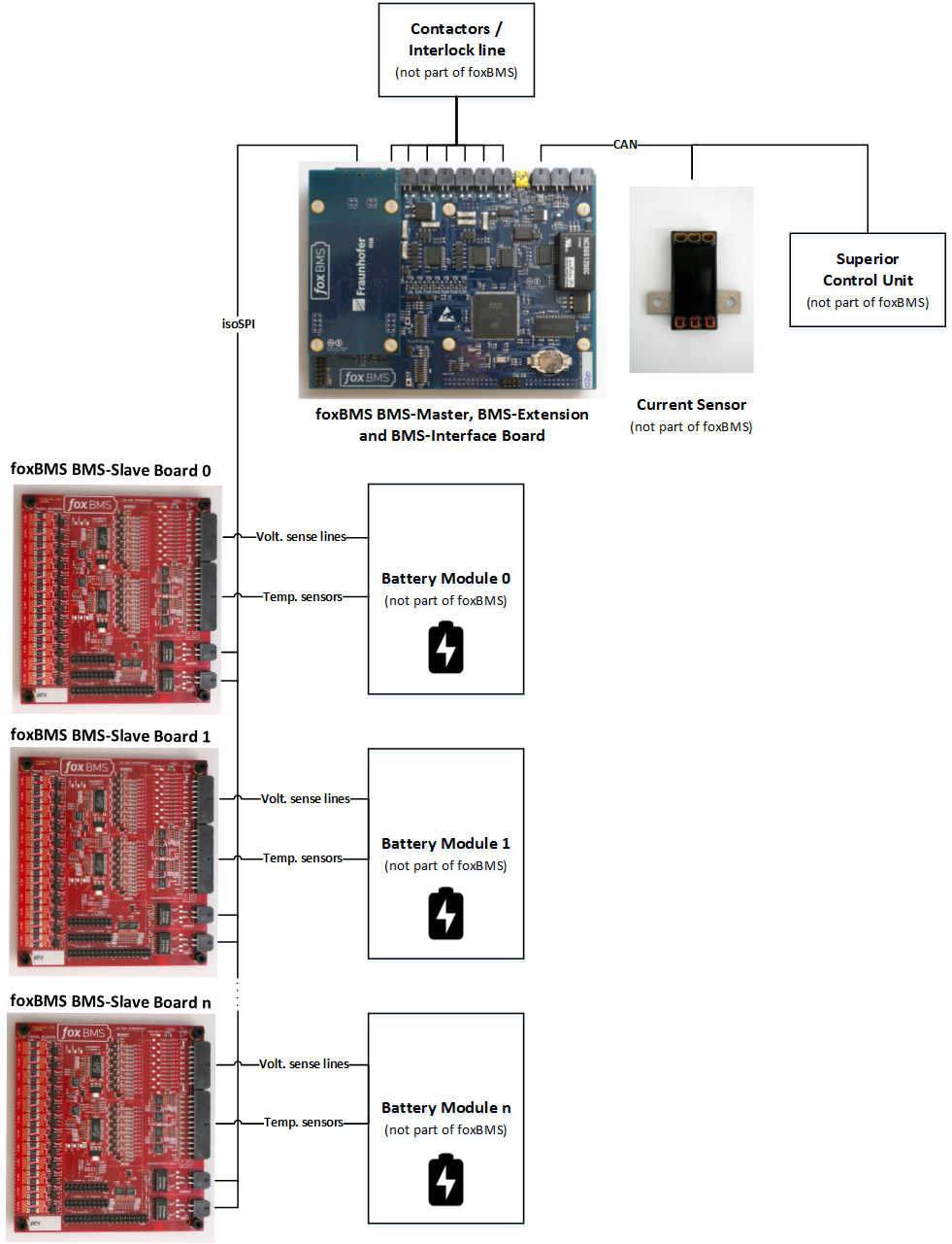
Fig. 3.1 High level overview of foxBMS 2
In the case that an application requires more inputs, outputs or specific hardware functions, these can be implemented through a BMS-Extension Board. This is a specialized board that connects through a set of connectors to the BMS-Master Board and can implement application-specific hardware for the foxBMS Master Unit.
This description reflects the current state of foxBMS 2. Due to the open nature of the system, many other possibilities can be implemented, like for example:
Use of other types of current sensors (e.g., shunt-based or Hall-effect based)
No foxBMS Slave Unit needs to be used: a direct measurement of the cell voltages and cell temperatures can be performed by the foxBMS Master Unit
A higher number of contactors can be controlled (e.g., up to 9)
etc…
