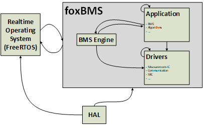
The following section describes the diagnostics and safety focused BMS software
architecture as depicted in Fig. 10.1.
A detailed version of the architecture is shown in
Fig. 10.2.
This view is exported from Axivion Bauhaus Suite and should be viewed
and verified in the tool itself for best performance.
A hardware abstraction layer (HAL) provides various interfaces to directly
access the hardware and its peripherals. This enables encapsulation of the
actual BMS software implementation from the hardware and eases porting the
foxBMS 2 software to different microcontrollers.
The open-source real-time operating system FreeRTOS is the centerpiece of
the software architecture.
Its reliable kernel is ideally suited to ensure the compliance of all soft and
hard real-time requirements of a battery-management system.
Furthermore, it provides a migration path to SafeRTOS, which includes
certifications for the medical, automotive and industrial sector, if a
certification is required by the application.
Three scheduled tasks with a period of 1ms, 10ms and 100ms are configured to
execute the various deterministic finite-state machines that describe the
behavior of the BMS.
Time-sensitive software modules (e.g., diagnostics, measurement,
CAN reception, …) are called within the 1ms task, whereas less time critical
modules (e.g., CAN transmission, interlock, BMS, …) are located
inside the 10ms task. Software modules that are temporally uncritical (e.g.,
state estimation, balancing, …) are handled by the 100ms task.
An additional asynchronous task is used to implement a data-exchange layer
between the different concurrent tasks and processes.
This data-exchange layer runs with the highest priority of all tasks and is
interfaced using queues either to send or to receive data.
These FreeRTOS queues are formally verified for memory safety, thread safety
and functional correctness.
The foxBMS software itself is grouped into three different layers:
A dedicated driver layer using the HAL interface provides different
communication interfaces (CAN, UART, SPI, …) monitor BMS peripherals, their
status (e.g., supply voltages, transceivers, …) as well ass the BMS slaves.
Diagnostic functions and error handling, system monitoring (for hard- and
software) and interfaces to the data-exchange layer are the most important
tasks of the BMS Engine.
The actual BMS implementation including the monitoring of the safety
parameters (e.g., safe-operating area, contactor state, communication
errors, …), state estimation functionalities (state-of-charge, state-of-
health, state-of-energy) and the vehicle specific BMS application is done
within the application layer.