The communication with the AFE is made via a daisy-chain, which means that all
the AFEs take part in every transmission.
There are 3 types of communications:
Sending a command without data (e.g., start a measurement).
Writing a register.
Reading a register.
Commands are sent to the whole daisy-chain, which means that for commands
the daisy-chain acts as a transmission line.
When reading and writing, the daisy-chain acts as a shift register.
The registers read or written are 6 bytes wide.
The data packets are made of bytes (8 bit words).
The driver was developed on a TI TMS570.
As the TI TMS570 SPI can transmit up to 16 bit per word, all HAL SPI function
work with 16 bit words.
As a consequence, all AFE functions work with 16 bit words, but each
word must only contain one byte (i.e., the value must not be greater than
255).
A common parameter to all AFE functions has the type ADI_STATE_s.
This structure is used to control the flow of the AFE driver.
The structure holds the following information:
A boolean indicating if the driver has been initialized or not, i.e., whether
the first measurement has been started or not.
A boolean set to true after the first measurement was made.
The number of SPI interfaces to be used.
Usually it corresponds to the number of strings in the system.
The number of the string currently addressed.
A table used to store the redundant GPIO channel being used.
This is an internal variable for the driver and should not be modified.
The serial IDs read from the AFEs in the daisy-chain.
The revision read from the AFEs in the daisy-chain.
A structure of the type ADI_DATA_s.
It is used to store pointers to all relevant data (e.g., measured cell
voltages, measured temperatures).
It also stores the command counter for each string and an error table
with all error flags.
The ADI_DATA_s structure contains the following data:
A pointer to the SPI receive and the transmit buffer
All measurements (e.g., cell voltages, cell temperatures, GPIO voltages)
The command counter for each AFE
The error table, a structure of the type ADI_ERROR_TABLE_s
An internal variable of the driver used for redundant auxiliary voltage
check.
The ADI_ERROR_TABLE_s structure contains the error status of the driver:
Flag indicating if PEC correct or not
Flag indicating if the command counter of the driver matches the internal
command counter of the AFEs
Flag indicating if the configuration read from the AFEs matches the written
configuration
4.33.1.1. Functions to adapt to change environment
The AFE driver in its current form is designed to work within foxBMS 2,
using FreeRTOS.
In order to use it in another environment (e.g., bare metal),
it must be adapted in the following places.
The function used in the AFE driver make use of the following enum
as return value:
/** enum for standard return type */typedefenum{STD_OK,/**< ok */STD_NOT_OK,/**< not ok */}STD_RETURN_TYPE_e;
It must be added if it is not defined.
Dedicated structures are used to store the data retrieved by the driver.
If they are not defined, the following definitions must be added:
/** data block struct of cell voltages */typedefstruct{int16_tcellVoltage_mV[ADI_NR_OF_STRINGS][ADI_NR_OF_CELL_BLOCKS_PER_STRING];/*!< unit: mV */}DATA_BLOCK_CELL_VOLTAGE_s;/** data block struct of GPIO voltages */typedefstruct{int16_tgpioVoltages_mV[ADI_NR_OF_STRINGS][ADI_NR_OF_MODULES_PER_STRING*ADI_NR_OF_GPIOS_PER_MODULE];/*!< unit: mV */int16_tgpaVoltages_mV[ADI_NR_OF_STRINGS][ADI_NR_OF_MODULES_PER_STRING*ADI_NR_OF_GPAS_PER_MODULE];/*!< unit: mV */}DATA_BLOCK_ALL_GPIO_VOLTAGES_s;/** data block struct of cell temperatures */typedefstruct{int16_tcellTemperature_ddegC[ADI_NR_OF_STRINGS][ADI_NR_OF_TEMP_SENSORS_PER_STRING];/*!< unit: deci °C */}DATA_BLOCK_CELL_TEMPERATURE_s;/** data block struct of balancing control */typedefstruct{boolactivateBalancing[ADI_NR_OF_STRINGS][ADI_NR_OF_MODULES_PER_STRING][ADI_NR_OF_CELL_BLOCKS_PER_MODULE];/*!< 0: no balancing, 1: balancing active */}DATA_BLOCK_BALANCING_CONTROL_s;/** data block struct of cell open wire */typedefstruct{uint8_topenWire[ADI_NR_OF_STRINGS][ADI_NR_OF_MODULES_PER_STRING*(ADI_NR_OF_CELL_BLOCKS_PER_MODULE+1u)];/*!< 1 -> open wire, 0 -> everything ok */}DATA_BLOCK_OPEN_WIRE_s;
They must be added at the place in code marked with:
/* If needed, add definition of database entries here */
in the file adi_ades183x_defs.h.
In the file adi_cfg.h, the following defines must be adapted:
ADI_NR_OF_STRINGS must be set to 1u if only one string is used.
If several strings are used, the SPI function must be adapted to take this
into account.
ADI_NR_OF_MODULES_PER_STRING is the number of modules in one daisy-chain
so corresponds to the number of AFEs in a daisy-chain.
ADI_NR_OF_CELL_BLOCKS_PER_MODULE is the number of cells connected to
an AFE.
ADI_NR_OF_GPIOS_PER_MODULE is the number of GPIOs available on an AFE.
It must be set to 10u.
ADI_NR_OF_TEMP_SENSORS_PER_MODULE is the number of temperature sensors
connected to the GPIOs.
It cannot be higher than ADI_NR_OF_GPIOS_PER_MODULE.
ADI_MAX_SUPPORTED_CELLS is the maximum number of cell voltage inputs
present on the AFE.
For the ADES1830, it must be set to 16.
ADI_SpiTransmitReceiveData() is the function used to trigger
transmission over SPI.
It takes four parameters:
a struct of the type ADI_STATE_s, which is used to determine which
string has to be addressed
a pointer to the transmit buffer
a pointer to the receive buffer
the number of bytes to be transmitted
Three cases must be considered, each contained in
the markers
/* START SPI function to adapt for different environment *//* Code to be defined here to make SPI transmission *//* END SPI function to adapt for different environment */
in the code.
There are three cases to consider:
case 1: if a length of 0 is used, this means that the function must only send
a dummy byte.
if a length greater than 0 is used:
case 2: if the pointer to the receive buffer has the value NULL_PTR, this
means that the function has only data to transmit and that the data
received on the SPI interface is discarded.
case 3: otherwise the function transmits and receives data.
Warning
For the last two cases, before the data transmission and/or reception,
a dummy byte must be sent to wake up the AFE communication interface.
The function ADI_AccessToDatabase() is used to store and retrieve the
data from the foxBMS 2 database.
If the database is not used, the function content can simply be removed.
The function ADI_Wait() receives an integer parameter.
The function must wait for the number of milliseconds passed as parameter.
In foxBMS 2, it blocks the FreeRTOS task running the AFE driver.
The AFE driver looks for requests to start or stop.
Requests are made made with the extern function ADI_MakeRequest().
The static function ADI_GetRequest() is used to retrieve the requests
made to the driver.
In foxBMS 2, a FreeRTOS queue is used.
If this environment is not used, the request mechanism must be adapted
accordingly and the reference to the queue must be removed if the queue is not
used.
If the request mechanism is not needed or for debugging purposes, the
function ADI_GetRequest() can simply be changed to always set the
request to ADI_START_REQUEST.
The functions OS_EnterTaskCritical() and OS_ExitTaskCritical() are
used to prevent interrupts during the setting of the flags to ensure the
validity of the flags.
They must be replaced by an appropriate protection mechanism if FreeRTOS
is not used.
In foxBMS 2, a FreeRTOS queue is used in the function ADI_MakeRequest().
If this environment is not used, the request mechanism must be adapted
accordingly and the reference to the queue must be removed if the queue is
not used.
As explained above, if requests are not needed or for debugging
purposes, if the function ADI_GetRequest() is changed to always set the
request to ADI_START_REQUEST, the function ADI_MakeRequest() can
simply be changed to do nothing.
The function ADI_ActivateInterfaceBoard() is used to drive an I2C port
expander, to toggle activation pins in order to activate the interface board
communicating with the slave.
It must be adapted to the hardware used.
The function ADI_ConvertGpioVoltageToTemperature() converts a GPIO
voltage in mV to a temperature in deci Celsius.
It must be adapted to the hardware used.
As stated before, the communication with the daisy-chain is made via three
basic operations.
They are detailed in this section.
Each transaction with the daisy-chain starts with a command.
It is then followed by data when reading from or writing to the AFE,
or by nothing for command not involving data (e.g., when triggering
a measurement).
Each command is accessible via a dedicated variable, like
The function ADI_TransmitCommand() is used for this purpose.
It has four parameters:
a uint16_t pointer.
As commands sent to the AFE are made out of 2 bytes, it must point to two
bytes, corresponding to the used command as defined in the data sheet.
One of the commands defined as explained above must be used.
a pointer to the ADI_STATE_s structure.
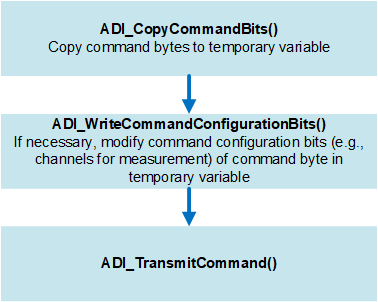
The functions to send commands are illustrated in
Fig. 4.11.
Some commands have configurable bits (e.g., measurement commands, in order
to change measurement parameters).
Base commands have been defined as constant variables and for concerned
commands, the configurable bits are set to 0.
The function ADI_TransmitCommand() takes the command
as a non-constant variable, so the following procedure must be used:
Use ADI_CopyCommandBits() to copy the constant command definition
to a non constant variable.
This variable must be an uint16_t table of length 4.
If necessary, use ADI_WriteCommandConfigurationBits() to modify
the configurable bits as needed.
Call ADI_TransmitCommand() with the non constant variable.
The function realizes the following operations:
The function computes the PEC of the two command bytes and then
sends 4 bytes (2 bytes command followed by two bytes PEC).
If the command sent increments the AFE command counter, the
command counter stored in the driver and accessed via the
ADI_DATA_s structure in the ADI_STATE_s structure is
increased.
The comparison between the AFE command counter and the
command counter stored by the driver is made in the function
ADI_ReadRegister(), as the AFE transmits its command counter
in each answer frame.
The function ADI_ReadRegister() is used for this purpose.
It has three parameters:
An uint16_t pointer to the command corresponding to the register to read.
One of the commands defined as explained above must be used.
A uint8_t pointer to the table where the read data is stored
A pointer to the ADI_STATE_s structure
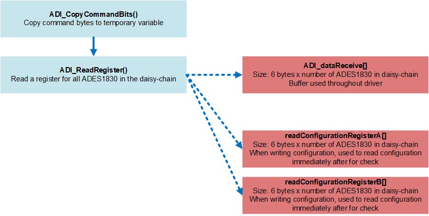
The functions and variables to read registers are illustrated in
Fig. 4.12.
Fig. 4.12 Functions and variables used to read registers
The function realizes the following operations:
The SPI transmit/receive function is used to transmit the command and
receive the data:
First the two bytes of the command must be transmitted, followed by the
two command PEC bytes.
The command PEC is computed with the PEC15 function.
Then the AFE ICs in the daisy-chain transform into a shift-register
to transmit the data to be read while the MCU receives it.
This data consists of one frame for each AFE.
Each frame contains 4 or 6 bytes, depending on the register size, followed
by two bytes of data PEC.
Data PEC is computed with the PEC10 function.
The function computes the PEC of each data frame and compare it to the
PEC sent by each AFE.
If it does not match, the corresponding crcIsOk variable in the
ADI_ERROR_TABLE_s structure is set to false.
It is set to true otherwise.
The function extract the command counter sent by each AFE and
compares it with the value stored in the driver in the ADI_DATA_s
structure.
If it does not match, the corresponding commandCounterIsOk
variable in the ADI_ERROR_TABLE_s structure is set to false.
It is set to true otherwise.
The variable
uint8_tadi_dataReceive[ADI_NR_OF_MODULES_PER_STRING*ADI_MAX_REGISTER_SIZE_IN_BYTES]
is a general purpose variable used throughout the driver as a buffer when
using the read function.
The function ADI_WriteRegister() is used for this purpose.
It has three parameters:
A uint16_t pointer to the command corresponding to the register to write.
One of the commands defined as explained above must be used.
A uint8_t pointer to the table where the data to be written is stored
A variable of the type ADI_PEC_FAULT_INJECTION_e used for fault
injection.
A pointer to the ADI_STATE_s structure
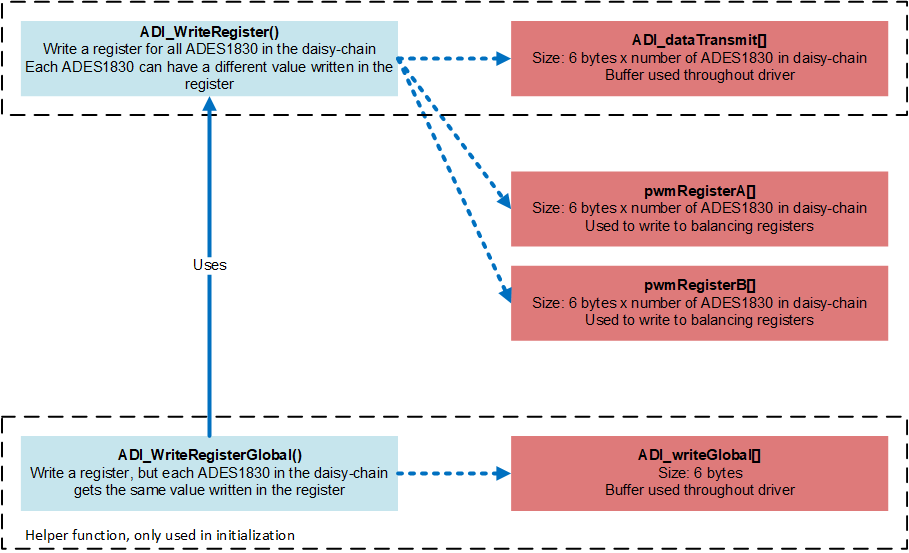
The functions and variables to write registers are illustrated in
Fig. 4.13.
Fig. 4.13 Functions and variables used to write registers
The function realizes the following operations:
The data to be sent for the transmission is prepared:
First the two bytes of the command must be transmitted, followed by the
two command PEC bytes.
Command PEC is computed with the PEC15 function.
Then the PEC of the written data must be computed.
This data consists of one frame for each AFE.
Each frame contains 4 or 6 bytes, depending on the register size, followed
by two bytes of data PEC.
Data PEC is computed with the PEC10 function.
The SPI transmit/receive function is used to transmit the command and
followed by the data.
After the command was received, the AFEs in the daisy-chain transform into
a shift-register to receive the data to be written while the MCU
transmits it.
The fault injection can be of 3 types:
ADI_PEC_NO_FAULT_INJECTION, the write process is made without
fault injection
ADI_COMMAND_PEC_FAULT_INJECTION, the write process is made and
the command PEC is modified so that it does not correspond anymore to the
command sent for writing
ADI_DATA_PEC_FAULT_INJECTION, the write process is made and
the data is modified so that it does not correspond anymore to the data
PEC sent
The variable
uint8_tadi_dataTransmit[ADI_NR_OF_MODULES_PER_STRING*ADI_MAX_REGISTER_SIZE_IN_BYTES]
is a general purpose variable used throughout the driver as a buffer when
using the write function.
The function ADI_WriteRegisterGlobal() is equivalent to
ADI_WriteRegister(), writing the same 6 bytes of data to
all AFEs in the daisy-chain.
It is a practical way to write the same data to all AFEs.
The variable uint8_tadi_writeGlobal[ADI_MAX_REGISTER_SIZE_IN_BYTES] is a
buffer used to write the same 6 bytes (ADI_MAX_REGISTER_SIZE_IN_BYTES
equals 6) of data to a register for all the AFE ICs in the daisy-chain.
uint16_tadi_bufferRxPec[ADI_N_BYTES_FOR_DATA_TRANSMISSION] and
uint16_tadi_bufferTxPec[ADI_N_BYTES_FOR_DATA_TRANSMISSION]
are the SPI buffers used during all transmissions.
The number of bytes is
(ADI_COMMAND_AND_PEC_SIZE_IN_BYTES+((ADI_MAX_REGISTER_SIZE_IN_BYTES+ADI_PEC_SIZE_IN_BYTES)*ADI_N_ADI))
or 4+(6+2)*ADI_N_ADI.
The transmission uses 2 bytes for the command, followed by 2 command PEC bytes,
followed by the data.
For each AFE in the daisy-chain, the transmission has maximum 6 bytes of data,
each followed by 2 data PEC bytes, hence the number of
data bytes being 6+2 time the number of AFEs in the daisy-chain.
In foxBMS 2, as the AFE driver uses SPI with DMA, these two variables MUST
reside in a non cache-able area.
These two variables are internal to the working of the AFE driver and should
not be used for other purposes.
4.33.1.4. Helper functions to access bit fields in registers
The function ADI_ReadDataBits() is used to extract a bit field from data
that has been read.
Its parameters are:
Read byte from daisy-chain, from which data field is to be extracted.
Pointer to memory location (1 byte) where extracted data field will be
written.
Position of bit field to extract.
Mask of bit field to extract.
The function ADI_WriteDataBits() is used to write a bit field in data
that has to be written.
Its parameters are:
Pointer to byte that will be written to daisy-chain, where data from bit
field will be written.
Byte containing data to be written to bit field.
Position of bit field to extract.
Mask of bit field to extract.
Bit field position and bit field masks are defined for all entries of all
configuration registers in adi_ades183x_defs.h.
When writing a bit field in a byte with ADI_WriteDataBits(), the other
bit fields in the byte remain unchanged.
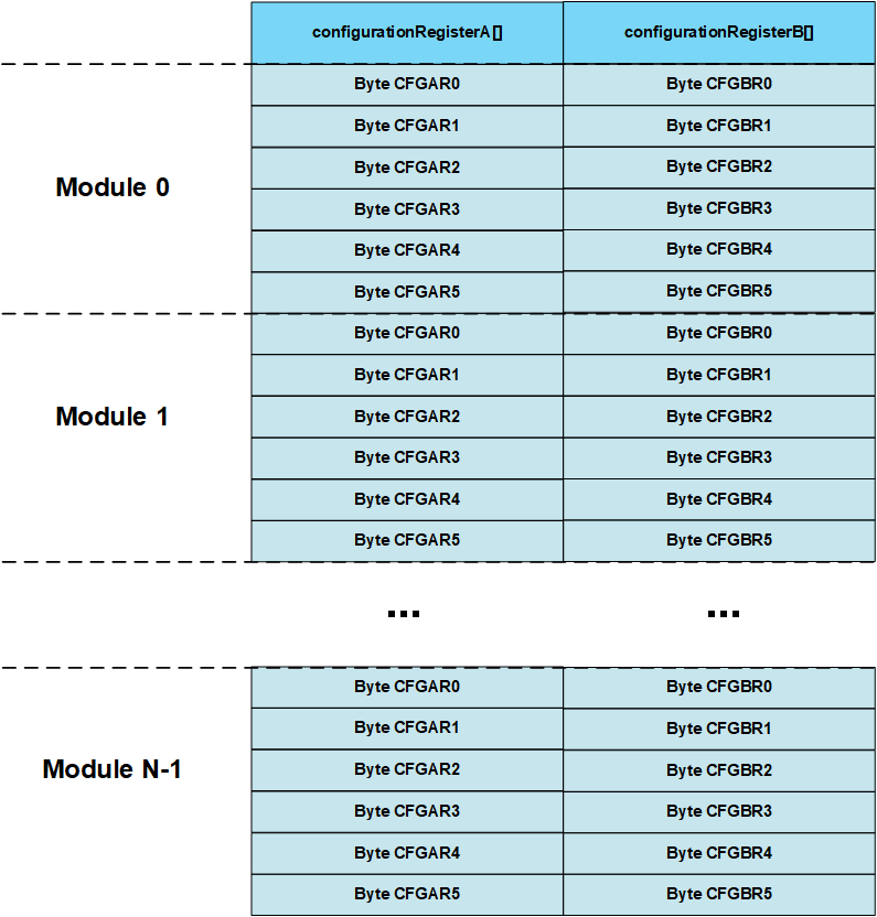
The driver should ensure that the configuration stored on the AFE ICs
in the daisy-chain corresponds to the configuration that was written.
As a consequence, the driver holds a copy of the configuration that is written
to the AFE ICs in the daisy-chain.
There are 2 tables, one for configuration register A and one for configuration
register B.
They are named adi_configurationRegisterAgroup[] and
adi_configurationRegisterBgroup[].
Both tables have the size
[ADI_NR_OF_STRINGS][ADI_NR_OF_MODULES_PER_STRING*ADI_MAX_REGISTER_SIZE_IN_BYTES]
where ADI_MAX_REGISTER_SIZE_IN_BYTES which equals 6u is the
register size in bytes: the content of each configuration register
must be stored for each AFE in the daisy-chain.
In addition, this must be done for each string.
In Fig. 4.14, the tables are
represented to ease the comprehension.
When writing the configuration, the driver also reads it to check that it was
written correctly.
For this purpose, another set of tables exists, named
adi_readConfigurationRegisterAgroup[] and
adi_readConfigurationRegisterBgroup[].
They have the same size as the variables used to write the configuration.
It must be noted that the figure only shows the tables for one string.
There is one configuration table set for each string.
The procedure to set a specific configuration is made out of two steps:
Change the configuration in the configuration tables
adi_configurationRegisterAgroup[] and/or adi_configurationRegisterBgroup[].
Write the configuration of the tables to the AFEs in the
daisy-chain.
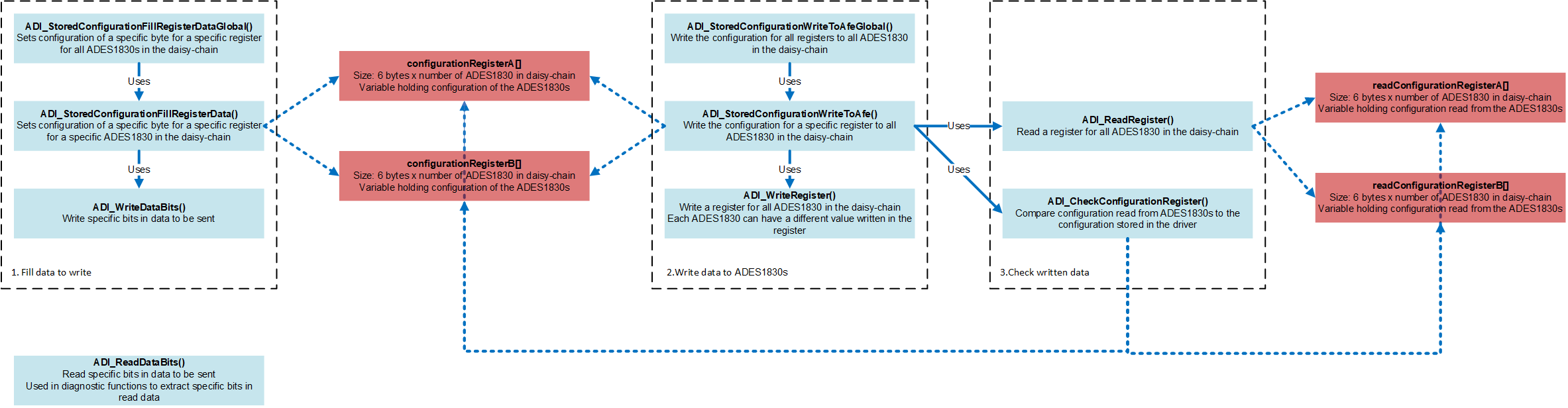
The functions to change configuration and their interaction with the
variables are illustrated in
Fig. 4.15.
Fig. 4.15 Functions and variables used to change configuration
Two functions are available change the configuration in the configuration
tables: ADI_StoredConfigurationFillRegisterData() and
ADI_StoredConfigurationFillRegisterDataGlobal().
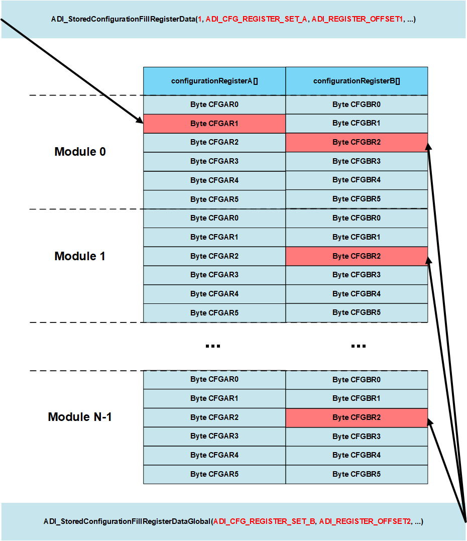
The function ADI_StoredConfigurationFillRegisterData() is used to
modify the values in a specific byte of a register, for one specific
IC in the daisy-chain.
Its parameters are:
Module number corresponding to the AFE whose configuration must be changed.
ADI_CFG_REGISTER_SET_e parameter.
Used to specify which configuration
register must be written (i.e., used to chose between register A and B).
Register offset: corresponds to the byte position in the register.
Defines are available in adi_ades183x_defs.h (ADI_REGISTER_OFFSET0 to
ADI_REGISTER_OFFSET0).
Data to be written to the bit field in the register.
Bit field position.
Bit field mask.
ADI_STATE_s structure.
The string number is passed via this structure.
ADI_StoredConfigurationFillRegisterData() uses ADI_WriteDataBits(),
so when writing a bit field in a byte, the other bit fields in the byte remain
unchanged.
The function ADI_StoredConfigurationFillRegisterDataGlobal() simply
calls ADI_StoredConfigurationFillRegisterData() for all modules in a
daisy-chain.
It is a useful and simpler way to set the same configuration
for all AFEs in the daisy-chain.
In Fig. 4.16, the use of the helper
functions to modify the configuration tables is represented to ease the
comprehension.
Fig. 4.16 Modification of tables holding configuration
4.33.1.5.2. Writing the changes to the daisy-chain
To write the changes to the daisy-chain, the function
ADI_StoredConfigurationWriteToAfe() must be called.
The first parameter is an enum of the type ADI_CFG_REGISTER_SET_e.
It serves to chose which register from the configuration tables to write and
can have values ranging, ADI_CFG_REGISTER_SET_A or
ADI_CFG_REGISTER_SET_B.
When called, the function ADI_StoredConfigurationWriteToAfe() writes
the data contained in the configurationRegisterX[] variable to the
daisy-chain.
For instance, if the function is called with ADI_CFG_REGISTER_SET_B as
first parameter, the content of adi_configurationRegisterBgroup[] will be
written to the daisy-chain.
It must be noted that even if the tables have been changed, the change will
not be written to the daisy-chain until the function
ADI_StoredConfigurationWriteToAfe() is called for the corresponding
register.
After the write operation is complete,
ADI_StoredConfigurationWriteToAfe() reads the register it has just
written to and stores the results in the table
readConfigurationRegisterX[], where X again corresponds to the
configuration register being accessed.
ADI_StoredConfigurationWriteToAfe() then calls
ADI_CheckConfigurationRegister().
This function compares configurationRegisterX[] and
readConfigurationRegisterX[].
If both table do not match, the corresponding (i.e., string and module number)
configurationIsOk variable in the ADI_ERROR_TABLE_s structure is set
to false.
It is set to true otherwise.
The function ADI_StoredConfigurationWriteToAfeGlobal() is used to write
all configuration register at once.
It simply calls ADI_StoredConfigurationWriteToAfe() for all configuration
registers.
ADI_StoredConfigurationWriteToAfe() and
ADI_StoredConfigurationWriteToAfeGlobal() use the primitives
ADI_WriteRegister() and ADI_ReadRegister() to communicate with
the daisy-chain.
The procedure to change the IIR filter setting for cell voltage measurement
for all AFEs in the daisy-chain is as follows.
The corresponding bit field is located in configuration register A, byte
CFGAR5, bits [2:0].
First, set the configuration in adi_configurationRegisterAgroup[] with
ADI_StoredConfigurationFillRegisterDataGlobal().
All bytes of the configuration register must be written during the transaction
but the function ADI_StoredConfigurationFillRegisterDataGlobal() only
changes the filter bit field in byte CFGAR5 of configuration register A, so
the other bit fields in this byte and the other bytes are written but with
their current value, which means they remain unchanged.
The principal function of the AFE driver is ADI_MeasurementCycle().
It must be called once (i.e., it must not be called periodically), because it
already implements the measurement loop.
A structure of the type ADI_STATE_s must be defined and passed as
a pointer.
It controls the flow of the driver.
The driver loop is structured as follows:
The driver starts making no measurements and check for a start
request.
As long as no request was received, the driver does nothing
except checking for a request.
When a start request is received, the driver calls the
initialization function ADI_InitializeMeasurement().
Then the driver performs a measurement cycle: it loops through all the
strings and measures all relevant values and manages balancing.
After the measurement cycle, the driver check if a stop request comes.
If yes, it goes back to the non-measuring state, waiting for a
start request.
If no, it performs another measurement cycle and the process goes on.
The variable firstMeasurementMade of the ADI_STATE_s structure
must be initialized with false.
Once one measurement cycle was made, it is set to true.
The variable measurementStarted of the ADI_STATE_s structure must be
initialized with false and is set to true of false depending on
the state of the driver.
The function resets the error table with ADI_ResetErrorTable().
Then for each string:
Send a dummy byte with ADI_WakeUp() to wake up the daisy-chain
Clear the command counter with ADI_ClearCommandCounter()
Set the default configuration of the AFE in two steps.
First, write the tables adi_configurationRegisterAgroup[] and
adi_configurationRegisterBgroup[], which is done in
ADI_InitializeConfiguration().
Then call ADI_StoredConfigurationWriteToAfeGlobal() to write the
tables to the daisy-chain.
Check reset values of supply and reference measurements.
Clear values with the CLRAUX command.
Check cleared values of supply and reference measurements.
Set all PWM balancing values to 0.
Clear all flags in Status Register Group C with the CLRFLAG command.
Issue an ADCV command to set continuous measurements of C-ADCs and
S-ADCS (S-ADCs are redundant measurements).
Issue an ADAX command to measure all GPIOs and all other voltages like
supply and references.
Issue an ADAX2 command to measure one GPIO redundantly.
Wait 10 ms.
Issue a SNAP command to freeze values in voltage registers .
Get the cell voltages with ADI_GetVoltages().
This function reads the registers and stores the data in the
chosen structures pointed by the ADI_DATA_s structure.
Wait 8 ms.
18 ms is the time needed for the ADAX command to complete.
Read the GPIO voltages with ADI_GetGpioVoltages().
This function reads the auxiliary registers and stores the data in the
chosen structures pointed by the ADI_DATA_s structure.
Convert the GPIO voltages to temperatures with ADI_GetTemperatures().
This function stores the temperatures in the structure pointed by the
ADI_DATA_s structure.
If the first measurement flag was not set, set it.
Read the balancing orders and activate balancing accordingly with
ADI_BalanceControl().
Realize diagnostic functions with ADI_Diagnostic()
(This is a dummy function).
The functions that retrieve data from the daisy-chain call the function
ADI_ReadRegister().
The balancing control is done by writing to the configuration registers.
The driver reads in the table adi_balancingControl which cells have to
be balanced.
For cell voltages, the function ADI_GetVoltages() must be used.
Its first parameter is the ADI_DATA_s structure containing the state
of the driver.
Two parameters are also passed:
ADI_VOLTAGE_REGISTER_TYPE_eregisterType: it is used to determine
which register set must be read.
Possible values:
ADI_CELL_VOLTAGE_REGISTER to read cell voltage register (RDCVx)
ADI_AVERAGE_CELL_VOLTAGE_REGISTER to read average cell voltage
registers (RDACx)
ADI_FILTERED_CELL_VOLTAGE_REGISTER to read filtered cell voltage
registers (RDFCx)
ADI_REDUNDANT_CELL_VOLTAGE_REGISTER to read S-voltage registers
(RDSVx)
ADI_VOLTAGE_STORE_LOCATION_estoreLocation: it is used to determine
in which variable the read values will be stored.
Possible values:
ADI_CELL_VOLTAGE: store in data.cellVoltage
ADI_AVERAGE_CELL_VOLTAGE: store in data.cellVoltageAverage
ADI_FILTERED_CELL_VOLTAGE: store in data.cellVoltageFiltered
ADI_REDUNDANT_CELL_VOLTAGE: store in data.cellVoltageRedundant
ADI_CELL_VOLTAGE_OPEN_WIRE_EVEN: store in data.cellVoltageOpenWireEven
ADI_CELL_VOLTAGE_OPEN_WIRE_ODD: store in data.cellVoltageOpenWireOdd
Care must be taken when choosing the parameter values because registerType
and storeLocation are independent.
Calling for instance
For GPIO voltages, the function ADI_GetGpioVoltages() must be used.
Its first parameter is the ADI_DATA_s structure containing the state
of the driver.
Two parameters are also passed:
ADI_AUXILIARY_REGISTER_TYPE_eregisterType: it is used to determine
which register set must be read.
Possible values:
ADI_AUXILIARY_REGISTER to read GPIO voltage register (RDAUXx)
ADI_REDUNDANT_AUXILIARY_REGISTER to read average cell voltage
registers (RDRAXx)
ADI_AUXILIARY_STORE_LOCATION_estoreLocation: it is used to determine
in which variable the read values will be stored.
Possible values:
For commands, PEC15 is used.
It is a 15 bit CRC with polynomial 0xC599 and seed 0x10.
For data, PEC10 is used.
It is a 10 bit CRC with polynomial 0x48F and seed 0x10.
It is computed on the 6 bytes of data plus the 6 bits of the command counter.
For data to be written to the daisy-chain, the command counter bits are set to
0.
The scripts and documentation for the precomputed CRC tables are found at
tools/crc/crc-15_0xc599.md and tools/crc/crc-10_0x48f.md.
A C-implementation for the CRC pre-computation could look like this:
adi_voltageInputsUsed[] is used to skip cell voltages.
It contains 16 times the value 1.
All voltages are measured by the AFE but any value replaced by 0 will
result in the corresponding measured cell voltage input to be skipped when
storing the cell voltages.
Warning
The number of 1 must correspond to
BS_NR_OF_CELL_BLOCKS_PER_MODULE.
adi_temperatureInputsUsed[] is used to skip GPIO voltages.
It contains 10 times the value 1.
All GPIOs are measured by the AFE but any value replaced by 0 will result
in the corresponding GPIO voltage input to be skipped when storing the
temperatures.
Warning
The number of 1 must correspond to
ADI_NR_OF_TEMP_SENSORS_PER_MODULE.
Define a variable to hold the command information.
Copy the command information to it.
Optionally, set the desired values for configuration bits in the
command.
Call ADI_ReadRegister().
The results are stored in the table passed as parameters.
The table adi_dataReceive[ADI_NR_OF_MODULES_PER_STRING*ADI_MAX_REGISTER_SIZE_IN_BYTES]
can be used.
Typically, loop through all modules to extract the needed bytes.
ADI_ReadDataBits() can be used to extract a specific field.
Defines are available in the file adi_defs.h.
ADI_MAX_REGISTER_SIZE_IN_BYTES has the value 6.
Code example to read Status Register Group C:
uint16_tadi_command[ADI_COMMAND_DEFINITION_LENGTH]={0};ADI_CopyCommandBits(adi_cmdRdstatc,adi_command);ADI_ReadRegister(adi_command,adi_dataReceive,adi_state);for(uint16_tm=0u;m<ADI_N_ADI;m++){/* Get STR5 */uint8_tstatusData=adi_dataReceive[(m*ADI_RDSTATC_LEN)+ADI_REGISTER_OFFSET5];/* Check COMP flag */uint8_tflagComp=0u;ADI_ReadDataBits(statusData,&flagComp,ADI_STCR5_COMP_POS,ADI_STCR5_COMP_MASK);if(flagComp!=1u){adi_state->data.errorTable->compFlagIsCleared[adi_state->currentString][m]=false;}}
The function ADI_WriteRegister() is used to write a register.
The command information is passed directly to the function.
The table adi_dataTransmit[ADI_NR_OF_MODULES_PER_STRING*ADI_MAX_REGISTER_SIZE_IN_BYTES]
can be used to store the data to write.
The parameter pecFaultInjection should always have the value
ADI_PEC_NO_FAULT_INJECTION, otherwise faults will be injected and
the write operation will not be valid.
If the same data must be written to all AFEs in the daisy chain, the
function ADI_WriteRegisterGlobal() can be used.
The parameters are similar except for the data table: it is only 6 bytes wide.
The table
adi_dataTransmit[ADI_NR_OF_MODULES_PER_STRING*ADI_MAX_REGISTER_SIZE_IN_BYTES]
can be used to store the data to write.
Code example to write PMW Register Group A, same 6 bytes for all AFEs in the
daisy-chain:
The variable adi_writeGlobal[ADI_MAX_REGISTER_SIZE_IN_BYTES] can be
used to hold the 6 bytes that must be written in the desired register for
AFEs in the daisy-chain.
Define a variable to hold the command information.
Copy the command information to it.
Optionally, set the desired values for configuration bits in the
command.
The function ADI_WriteCommandConfigurationBits() is
available for this purpose.
Defines are available in the files adi_ades183x_defs.h and
adi_ades1830_defs.h for the setup bits.
The last parameter must be NULL_PTR when no data is sent with the
command.
The CLRFLAG command must be sent with data to indicate which flags must be
cleared.
The variable adi_clearFlagData[ADI_CLRFLAG_DATA_LENGTH] can be
used for this purpose.
ADI_CLRFLAG_DATA_LENGTH has the value 6.
adi_clearFlagData[] must be set without the desired value and passed
instead of NULL_PTR.